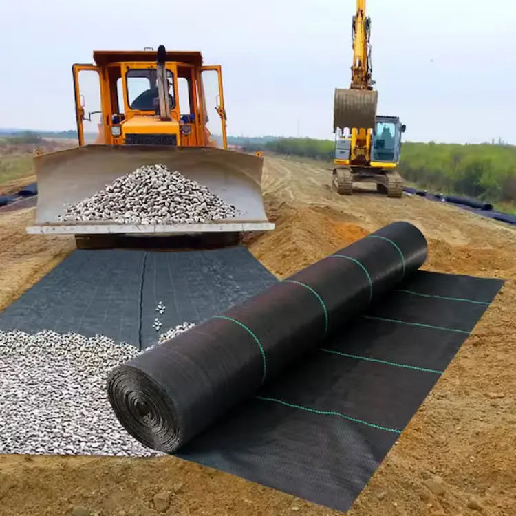
You can call this a reinforced soil wall, a geogrid, or a geosynthetic-reinforced soil wall. It’s also known as a geogrid-reinforced retaining wall.
 Project overview
 Project overview
A mountain road widening from K12+340 to K12+485 needed two traffic lanes. The slope was steep at 1:1.5, and the site width was narrow. Benching wasn’t an option. After studying the geology, we found that the top 2 m was low-liquid-limit clay. Below that, there was heavily weathered tuff. The allowable bearing capacity is 400 kPa, and there is no groundwater seepage. The team chose a reinforced soil solution. They used a biaxial tensile polypropylene geogrid.
Key design inputs
Reinforcement:
Biaxial polypropylene geogrid
Ultimate tensile strength: 50 kN/m
Creep reduction factor: 0.35
Construction damage reduction factor: 1.2
Wall geometry: total height is 10.0 m. It has two tiers with a 1.5 m-wide berm between them. Each tier is 5.0 m tall.
Facing: precast concrete modules with a 10° backward batter. Each module is 140 mm thick, 200 mm high, and 400 mm long. The back faces have interlocking teeth or slots. These help engage and hang the geogrid.
Stability and internal reinforcement layout
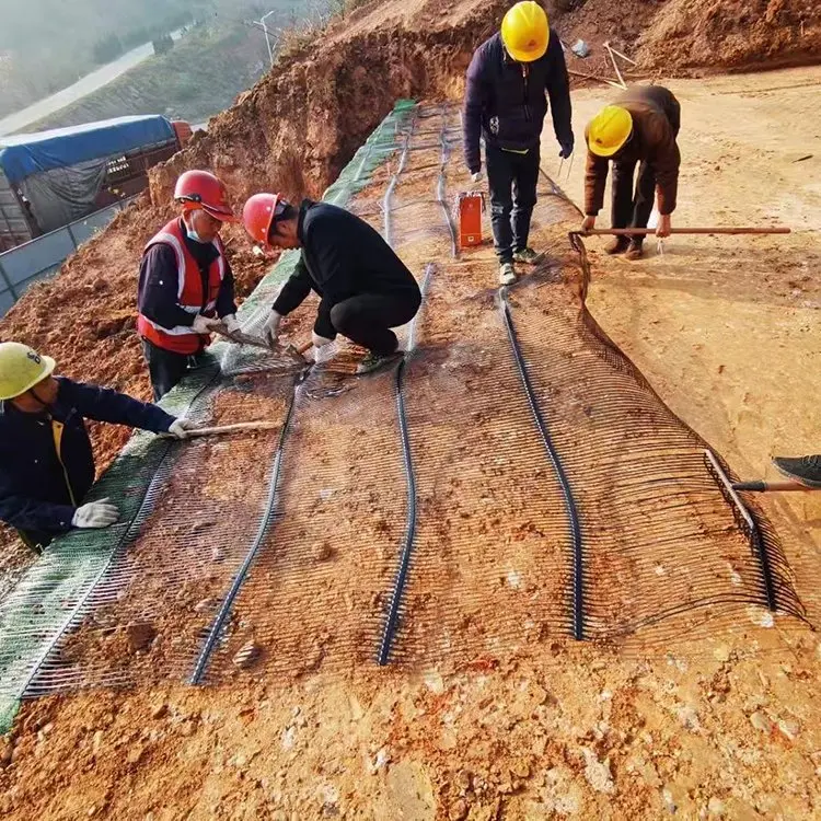
We managed potential sliding by using geogrids. We applied an “equal spacing, variable length” method. This setup helps to intersect likely slip surfaces.
Global stability (Bishop method) yields a factor of safety of 1.35. Check internal stability with a tie-back wedge model. The design load on each geogrid layer equals 0.4 times the short-term tensile strength of the geogrid.
Horizontal spacing: Bottom reinforcement layers are 0.40 m apart. The spacing increases to 0.60 m near the top.
Length distribution:
Below mid-height: geogrid length is 0.8 × wall height (0.8H).
Above mid-height: reduced to 0.5H.
Someone folds back the top layer. It’s wrapped with a 1.2 m embedment length and anchored into the fill using U-shaped staples.
Facing Connection:
Least lap width between adjacent geogrid sheets: ≥ 300 mm.
Secured with plastic clips.
Backfill, compaction, and friction requirements.
Backfill: well-graded crushed stone; largest particle size < 100 mm.
Compaction: Aim for a compaction degree of 95% or more (Standard Proctor). Use field nuclear densitometer testing in 30 cm layers to check compaction. Also, ensure the soil–geogrid interface friction angle is greater than 34°.
Drainage and waterproofing
The team designed drainage and seepage control together.
Toe drain: a cast-in-place concrete drain 500 mm × 500 mm at the wall toe.
Horizontal barrier: a 500 mm thick clay cutoff layer sits on the original slope. It has a 4% gradient and connects the toe to a longitudinal blind drain.
Internal Drainage:
Install one row of Ø50 mm flexible drainage pipe at a vertical interval of 1.5 m.
Wrap the pipe with non-woven geotextile.
Ensure you slope it 2% backward to discharge into the slope drain.
Coping: 300 mm wide reinforced concrete coping. It has Ø10 mm HRB400 reinforcement in two directions. This design helps prevent rainfall from infiltrating the wall face.
Construction sequence & quality control
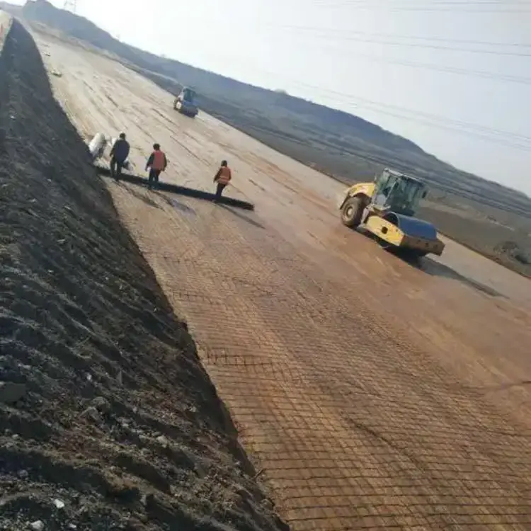
Construction followed the principle: stabilize slope → install reinforcement → backfill. Main controls included:
Clear and seal the slope with 50 mm of C20 concrete.
Install the geogrid from the top down. Lay the geogrid, then tamp it down. Make sure there are overlaps of at least 300 mm. Secure it using plastic fasteners.
Install precast facing modules with a spirit level. Check the total station every 2 meters of rise. The wall surface flatness must be ≤ 10 mm/m.
Backfilling and compaction proceeded in sync with rolling. Keep compactors at least 1.5 m from the panel face. Use small vibratory rammers within 0.8 m of panels to prevent disturbing the geogrid.
Monitoring results (post-construction performance)
Six months after completion:
Largest horizontal crest displacement: 7.4 mm, below mid-height (about 0.074% of wall height).
Geogrid strain shows a pattern: it’s “large in the middle, small at the ends.” The largest measured strain is 1,200 µε (microstrain), which is 48% of the allowable design strain. This means the geogrid has plenty of reserve capacity and is not at risk of long-term creep.
**Drainage Performance:** Outlet flow changed with the rainy season. Yet, there was no turbidity. This confirms that the waterproofing and drainage system is working well.
Project outcomes and lessons
This geogrid retaining wall design widened the road in a tight space. It features a 10 m high wall and a 2.5 m land take. This approach saved about 45% on earthwork volume. Plus, it cut the construction time by 30 days compared to traditional methods. The case offers a repeatable set of inputs. These inputs help with geogrid selection, layer layout, and construction controls. This is especially useful for slope widening projects in tight spaces.