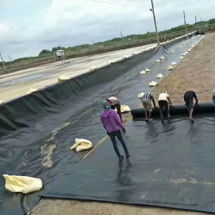
Bentonite Waterproofing Blanket, a specialized geosynthetic material, is engineered for seepage prevention in:
- Artificial lakes/water features
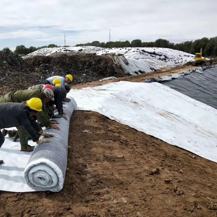
- Landfill liners
- Underground garages
- Rooftop gardens
- Reservoirs
- Oil storage facilities
- Chemical containment areas
Composition & Manufacturing:
Sandwiching high-swelling sodium bentonite between a composite geotextile and non-woven fabric, the blanket is manufactured through needle-punching. This process creates micro-fiber compartments that:
- Immobilize bentonite particles (preventing directional migration)
- Enable uniform hydration upon water contact
Waterproofing Mechanism:
When hydrated, the bentonite forms a continuous, homogeneous, high-density colloidal gel barrier within the blanket structure, delivering exceptional fluid containment performance.
1. Subgrade (Support Layer/Base Course) Preparation
(1) Subgrades classify as soft or rigid foundations. Before GCL installation:
- Compact to ≥85% density (Standard Proctor)
- Achieve ≤20mm surface irregularity
- Eliminate voids and protrusions >20mm
(2) Prohibit toxic substances in artificial lake foundations
(3) Ensure surface dryness; drain visible ponding
(4) Maintain corner radii:
- Minimum radius: 30cm
- For radii >40cm/vertical faces: Install perimeter anchors with compaction control
(5) Stabilize penetrating pipes with non-shrink concrete collars
(6) Excavate and compact anchor trenches as specified
2. Pre-Installation Requirements
(1) Perform material take-off; generate GCL layout and cutting diagrams
(2) Inspect GCL for defects (mechanical damage, voids); document and repair
(3) Install only in dry conditions. Cover immediately with polyethylene sheeting during precipitation to prevent premature hydration
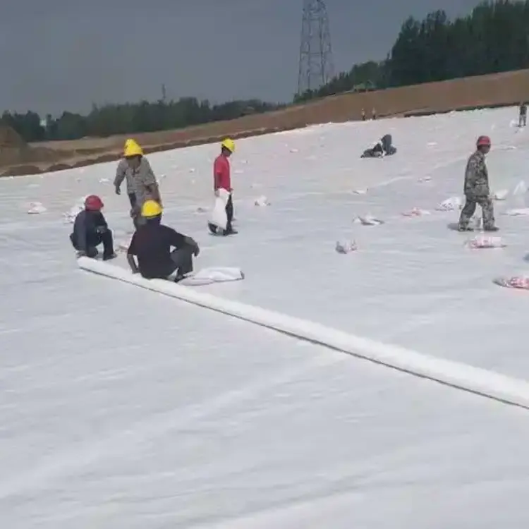
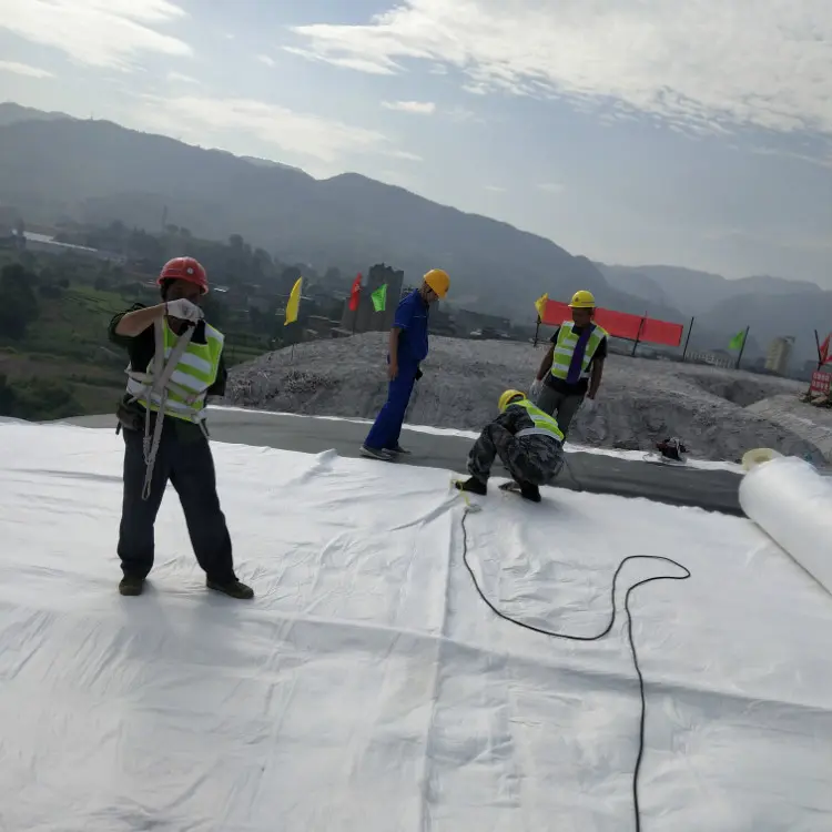
3. GCL Installation Protocol
(1) Use mechanical deployment for wide rolls; manual handling permitted for narrow rolls
(2) Install sequentially in zoned blocks per design orientation
(3) Stagger adjacent panel seams (minimum 300mm offset)
(4) Clean overlap surfaces of debris/moisture before joining
(5) On slopes >15°:
- Secure with corrosion-resistant pins/washers (500mm spacing)
- Orient roll length parallel to slope
- Treat pin penetrations with bentonite paste
(6) Orient non-woven geotextile toward water-facing surfaces
(7) Pipe penetrations: - Stabilize base with concrete
- Seal annulus with bentonite powder
- Band-secure GCL within 200mm of pipe
(8) Hydraulic applications (per SL/T 225): - Overlap downgradient (upper sheet over lower sheet)
- Minimum upstream overlap: 300mm
(9) Allow 100mm slack folds for subsidence; extend 100mm above design waterline
(10) Highway projects: Comply with JTJ/T 019-98 specifications
(11) Anchor trenches: 400mm × 400mm; backfill with compacted native soil
(12) Maintain contact with subgrade without wrinkles or bridging
(13) Employ overlaps where panel dimensions are insufficient
(14) Overlap procedure: - 200-250mm overlap width
- Apply 0.4kg/m² bentonite powder in 150mm band
- Moisturize and compact joint
(15) Repair defects immediately: - Patch holes with bentonite paste + 150mm oversized GCL patch
- Treat edges as overlaps
4. Backfilling Operations
Commence within 48 hours post-installation
Protection Layer Options:
- Option A: 300mm compacted lean clay (≥95% density)
- Option B: 50-100mm plain concrete
- Option C: 200mm sand + 50mm concrete + gravel
- Vertical surfaces:
- Single-brick retaining wall OR
- 30-40mm reinforced concrete (wire mesh required for heights >500mm)
Backfill Specifications:
① Complete within 48 hours of GCL placement
② Use sand/screened soil (max. aggregate size: 10mm)
③ Compact in 500mm lifts to ≥85% density
④ Prevent mechanical damage to GCL during compaction
⑤ Maintain minimum 300mm cover thickness